Please see All Flex Solutions' Technical Paper below, outlining best practices when it comes to bending considerations in flexible circuits and rigid flex applications.
Flexible circuits and rigid flex circuits are great enablers for electronic designers who desire more functionality in their projects. Both technologies allow the electronics to be formed to fit the device, rather than the device accommodating the electronics.
These packaging methods have been popular for many years, and designers are keen to understand the minimum bend radius guidelines, particularly for high reliability flex and rigid flex designs.
Following the recommended minimum bend radius guidelines will give you a flexible circuit capable of hundreds of thousands of bend cycles without failure.
There are two main categories of applications for flexible circuits – flex to install and dynamic flex. Flex to install applications are where the flexible circuit is completed, assembled, and then inserted into a device requiring usually no more than a few bends of the flexible area of the part. Dynamic flex is when the designer needs a flexible circuit that can withstand repeated bend cycling over the life of the part, without circuit failure.
In certain end applications, a flex to install circuit experiences dynamic flexing during its life. Many end use environments have high vibration, which can cause the flexible circuits to bend repeatedly, exposing your part to repeated bend cycling, which can cause failure. It is important to consider your end use, and then design accordingly.
High reliability flex circuit designers always specify RA or rolled annealed copper foil on the flexible layers of their designs. Rolled annealed copper foil typically has elongation values above 20% meaning they can be stretched more than 20% without breaking or fatigue of the copper.
A good starting point for minimum bend radius for designs using RA copper foil is 6X the composite thickness of the flexible area for one and two-layer designs, and 12X the composite thickness for three layers and more. These guidelines date back to the original Mil-Std 2118 for high reliability flexible circuit applications, and the material supplier recommendations as well. The thickness is measured over the composite, which would include any coverlayers, bondplies, shielding films, etc.
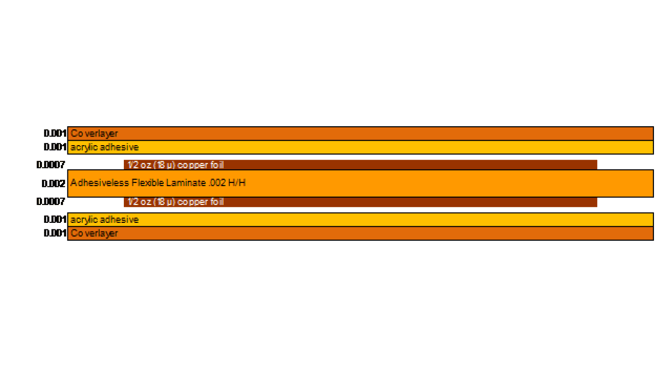
A double-sided example is shown in Figure 1. The base laminate is .002” (.05mm) thick with 18µ copper on both sides. Both sides also are covered with coverlayer at .002” (.05mm) thick. The overall thickness including copper is .0074” (.19mm) thick. Multiplying this thickness by 6 yields a minimum bend radius of .044” (1.12mm).
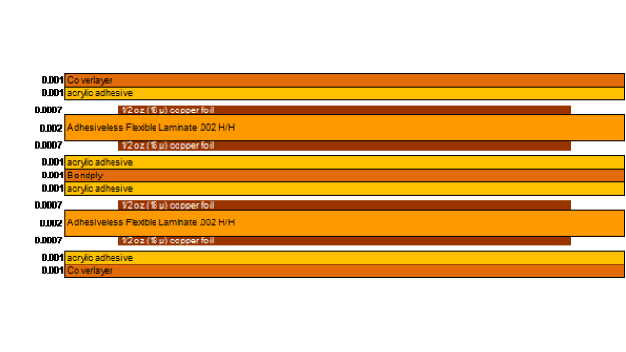
A four-layer flexible composite is shown in FIgure 2. Adding up the material thicknesses yields .0138” (.35mm). Multiply by 12 gives you a minimum bend radius of .166” (4.22mm). On multilayer designs it is best to put any ground/power planes on the outerlayers of the flexible sections of the part, to reduce stress and strain on the circuit layers, which are best routed on the internal layers.
The microsection photograph shown in Figure 3 is a four-layer flex (layer three circuitry is not visible) .022” (.56mm) thick. Multiplied by 12 results in a minimum bend radius recommendation of .264” (6.7mm). The flex shown above was bent 180° resulting in a bend radius of .031” (.79mm). Note, the two left-hand external layers have been elongated, and the right-hand internal layer is compressed. Also note the distortion and degradation of the coverlayer on the inside bend.
What if you need a smaller bend radius? What can be done? There are quite a few options for your design.
- Reduce the width of the flexible sections.
- Use thinner materials.
- Specify grain direction.
- Specify isolated or button plating on flexible sections.
- In multilayer constructions, you can un-bond the flexible layers.
- You can increase the length of the flexible layers, thereby providing more room for the bend radius.
- You can use a cross hatch pattern for the ground and power planes.
- You can put routed slots along the flexible section of the part, which works to increase the length of the flex.
- You can have the flexible section of the part peel away from the stiffener or rigid section of a rigid flex part.
Reduce the width of the flexible sections – the wider the flex arm, the less flexible it becomes. Reducing the width to the extent possible, makes the part more flexible.
Use thinner materials – the minimum bend radius is directly proportional to thickness of the flex composite. Thiner materials can be more difficult to work with but are still popular and allow the designer to accommodate designs with smaller bend radii.
Specify grain direction – the rolled annealed copper foil has a grain direction in one dimension and a bias, or non-machine direction in the other dimension. The laminate, and your part, will bend easier in the grain direction. You can specify on your print, what grain direction you prefer to accommodate the area(s) on your part that you would like to be most flexible.
Specify isolated or button plating – All Flex Solutions offers button plating on flexible circuits and flexible sections of rigid flex boards. When we isolate plate flexible circuits, we plate copper only in the vias and about a .002” (.05mm) ring on the outerlayer pads around the via. Building your part in this manner, eliminates the electroplated copper that would typically be plated onto the outerlayer circuitry. This makes your part much more flexible by eliminating the extra copper and the layering effect that reduces flexibility.
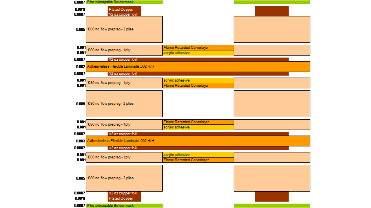
In multilayer constructions, un-bond the flexible layers – You can leave flexible layers un-bonded, creating two doublet sections, instead of one bonded four-layer section. See the six-layer rigid flex example in Figure 4.
The doublets have a minimum bend radius of 6X the composite thickness, instead of 12X, often opening options for the designer. A couple of notes of caution. In designs that require controlled impedance circuits on the flexible layers, the air gap acts as a dielectric and it is not possible to model the impedances. Also, in the end application, when bent, the independent flex layers can press in on each other, causing creasing and can sometimes violate the 6X minimum bend radius.
Increase the length of the length of the flexible section – designing outside the recommended minimum bend radius often occurs with flex sections that are too short. Increasing the length of the flex, allows more gradual bends.
Use cross hatched patterns for ground/power plane layers – cross hatched patterns on plane layers provides a much thinner composite with greater flexibility and is an ideal way to reduce the minimum bend radius on your designs. If the flex layers contain controlled impedance traces, have All Flex Solutions model them for you. Cross hatched reference planes have their own set of impedance modeling rules and All Flex has the experience to get the results you desire.
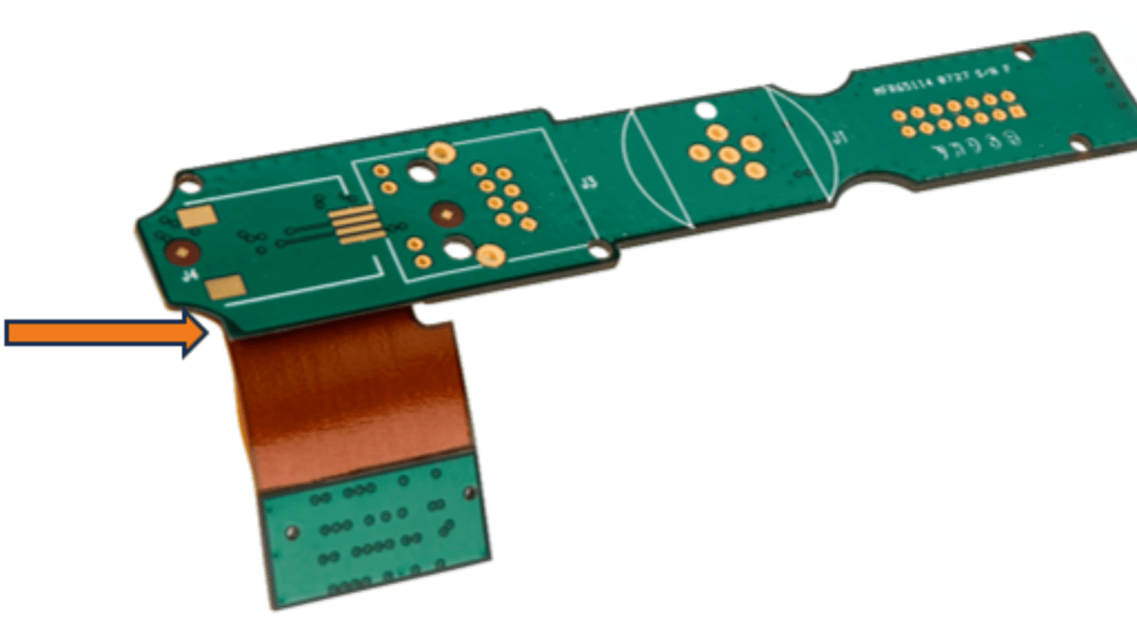
Add routed slots along the flex arms – If your design permits, you can rout slots along the sides of the flex arms. Routing these slots, permits the flex to peel away from the hardboard, before reaching the hardboard edge. An example of this technique is shown in Figure 5.
The recommendations above are conservative, and the IPC allows and suggests ways to reduce minimum bend radius guidelines as well. But these are good starting points for high reliability, never fail, flexible circuit electronics packaging.
Have the flex arm separate prior to meeting the edge of the board – In flex circuit constructions you can have the flex layers peel away from the stiffener, prior to reaching the edge of the stiffener. This increases the length of the flex arm, reducing the bend radius. It is possible to do the same with rigid flex, though rare, and it needs to be accommodated in manufacturing. An example of this feature is shown in Figure 6. Ask us for help on your design, to see if this technique would work for you.
Email or call us to review your application and design, and we are happy to share our thoughts and flexible circuit and rigid flex circuit design experience with you! For more information on bend radius guidelines for flexible circuits, contact Chris Eisenberg – CEisenberg@AllFlexInc.com, 507-663-7162.